EIGRP Floating Summarization

When you create summaries in EIGRP, the router automatically creates a route that points to a Null 0 interface.

This Null 0 interface serves as a bit bucket to prevent the router from forwarding traffic for destinations inside the summary address that it doesn’t have a longer match for. This is also known as Null routed.

This is true for OSPF and BGP summarization as well..

The administrative distance for summary routes have an AD of 5 by default. Knowing this we can configure a route with an AD of 1-4 to take precedence over our summary route.

Here is what I mean.

A simple EIGRP topology with R4, R5, and R8. Full EIGRP connectivity between nodes.

eigrp.summary0.PNG

Note: Lo1 has been created on R4 and R5 and advertised into the EIGRP process.

Lets configure a default route on R4 Ethernet segment towards R5.

eigrp.summary

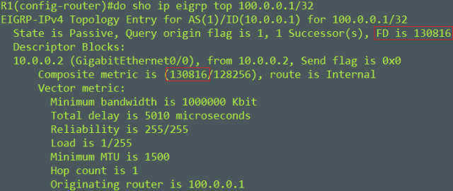
On R5, let’s check for the route to R4 Lo1 – 160.1.4.4. R5s CEF table matches our summary route to reach 160.1.4.4

eigrp.summary1

Let’s check on R8. R8 just like R5 has a CEF entry for 160.1.4.4 that matches the summary route 0.0.0.0/0 that R4 generated. R8 and R5 don’t have a specific route for 160.1.4.4 because the summary route it suppressing the more specific route from being install into their routing tables, which is why we need to consult the CEF for the route.

eigrp.summary2.PNG

R8 can pint 160.1.4.4 as of now.

Let’s configure a summary address for the Lo1 prefix’s on R5 for R8 on the shared Ethernet segment between them.

eigrp.summary3.PNG

Below you can see that R8 received our new summary address for the Lo1 prefixes. We can see this in the out put 160.1.4.0/23. Lets try to ping 160.1.4.4 – R4s Lo1.

eigrp.summary4.PNG

eigrp.summary7

Pings to R4 – 160.1.4.4 fail. Pings to R5 – 160.1.5.5 are successful because R5 has this address locally configured.

Lets see what R5 has to say about the route to 160.1.4.4.

eigrp.summary5

We can see that R5 can reach 160.1.4.4 via Null 0. Lets ping 160.1.4.4.

eigrp.summary6.PNG

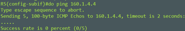
This can’t work! Our packets are Null routed!

So to get around this lets configure a static route on R5 to R4 for 160.1.4.4.

eigrp.summary8.PNG

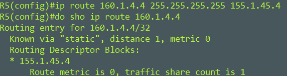
R5 now knows about 160.1.4.4 with a AD of 1. Let’s see if this fixes R8s reachability.

eigrp.summary9.PNG

R8 can reach 160.1.4.4!

This could have also been solved by poisoning the Null 0 interface from R5s RIB with an AD of 255.

eigrp.summary10.PNG

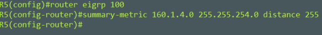
The difference here is that the Null 0 interface found on R5 is completely removed from the routing table.

Credit: INE

Mike

Advertisement

EIGRP Wide Metrics

EIGRP Classic metrics couldn’t differentiate between anything faster than 10 Gigabit Ethernet interfaces.

Below is the EIGRP classic composite metric

EIGRP composite cost metric = 256*((K1*Scaled Bw) + (K2*Scaled Bw)/(256 – Load) + (K3*Scaled Delay)*(K5/(Reliability + K4)))

This can be simplified to 256*(Scaled Bw + Scaled Delay)

Here is a break down of what this means

EIGRP uses one or more vector metrics in the calculation of the composite cost metric (the formula above), here they are.

Bandwidth
Delay
Load
Reliability

Out of these vector metrics Bandwidth and Delay are the most commonly used to produce the composite cost metric.

Metric weights are monitored by K values. The K values are integers from 0 to 128. The integers and the vector metrics, most commonly (bandwidth and delay) are used to calculate the overall EIGRP composite cost metric.

K1 and K3 are the only default constants used in the composite formula. (There are 5 K values) – K1,K3 = 1 K2,K4,K5 = 0

Here’s an example

eigrp.metric1

We want to find the composite metric between R1 and R2s lo100 – 100.0.0.1/32

First we need to get the Scaled Bandwidth with the below formula. The bandwidth of the link is 1G.

Scaled Bw = 10^7 / Interface Bandwidth

We have to express the 1G interface in Kilobits. Formula would look like this.

Scaled Bw = 10^7 / 1000000
Scaled Bw = 10000000 / 1000000
Scaled Bw = 10

Second we need to find the Scaled Delay with the below formula. The Delay is 5010 microseconds.

Scaled Delay = (Delay/10)
Scaled Delay = (5010/10)
Scaled Delay = 501

Note: Delay is cumulative along the path to the destination prefix.

Now we can fill in our simplified composite formula

256*(10 + 501) = 130861

Composite metric is 130861

eigrp.metric1


EIGRP wide metrics were introduced to assist in scaling for high bandwidth interfaces. EIGRP wide metrics offer the following:

  • 64 – bit metric calculation (compared to the 32 – bit metric of Classic EIGRP)
  • 128 – bit metric for the RIB
  • 65536 – Base Metric (compared to 256)
  • Bandwidth express in picoseconds (compared to tens of microseconds)
  • K6 ( reserved for future use and are known as “Extended Metrics”)
    • Jitter
    • Energy
    • Quiescent

Here is the wide metric formula

Metric = [(K1*Minimum Throughput + {K2*Minimum Throughput} / 256-Load) + (K3*Total Latency) + (K6*Extended Attributes)]* [K5/(K4 + Reliability)]

Bandwidth is now Throughput
Delay is now Latency.

Because we now have a larger base metric (65536) we can now account for higher speed links and because we use picoseconds this fixes delay issues.

Here are the simplified formulas for computing the composite cost metric. The vector metrics we care about are Throughput and Latency.

Composite Cost Metric = (K1*Minimum Throughput) + (K3*Total Latency)

To find Minimum Throughput use

Minimum Throughput = (107* 65536)/Bw)

For Total Latency interfaces under 1 Gigabit use

Total Latency for bandwidths below 1 gigabit  = (Delay*65536)/10

For Total Latency interfaces above 1 Gigabit use

Total Latency for bandwidths above 1 gigabit = (107* 65536/10)/ Bw

Lastly once you have your Composite cost metric divide it by the RIB metric of 128. This is so that the 64-bit metric calculation can fit into the RIB.

1392640 / 128 = 10880 – This is what will be installed into the RIB

eigrp.metric2

Some take aways

Although you can configure K values to produce varying routing behaviors, most configurations use only the delay/latency and bandwidth/throughput metrics by default so its best to keep K values to their defaults. Changing these could have a larger affect on more than just the EIGRP metric, for exmaple QoS will use these K values and if changed could have undesirable results.

It’s best to change the delay of the link to influence path selection, rather than changing the bandwidth. Changing the bandwidth could have a larger affect on more than just the EIGRP metrics.

K values still need to match between routers to form adjacency.

Mike